

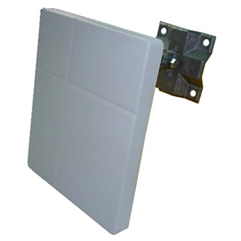
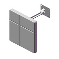
ANT58-1510PC MIMO antenna

Additional files
ANT58-1510PC_Spec_FWS_20100520.pdfProduct Introduction
DATA SHEET
| Model No. : | ANT58-1510PC |
| Description : | 4.9~5.9 GHz DUAL POLARIZATION PANEL ANTENNA |
| Date : | 2010/05/20 |
| Rev : | 1 |
-
OVERVIEW & SPECIFICATIONS
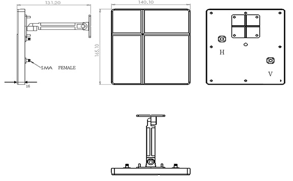
Electrical Specifications:
Frequency Range : 4.9~5.9GHz VSWR : ≤ 2.0 Impedance : 50Ω ± 5Ω Gain : 15dBi Polarization : Dual polarization Power Handling : 10 Watt Mechanical Specifications:
Connector : SMA FEMALE Operation Temp. : -30℃ ~ +60℃ Material : Radome: ABS
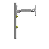
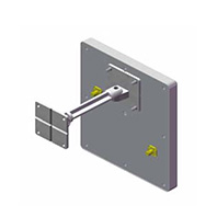
Mount: Zinc AlloyDimension (L*W*H) : 165.1*140.1*16 mm Weight : 190g ± 5g Color : White 3D Illustration
-
TESTING CONDITION
- 2.1 TEST SETUP
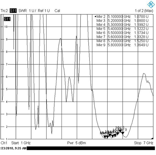
VSWR measurement (S11): Use ROHDE & SCHWARZ ZV8 Network Analyzer with Harbour RG-142 coaxial cable: 1000mm length in free space. - 2.1.1 VSWR
The table as below summarizes concern about Return loss measurement according to The frequency band is based on FWS design. The detail be shown as appendix that is from ROHDE & SCHWARZ ZV8 Network AnalyzerVSWR Performance Freq(MHz) 4900 5000 5100 Free space(port 1) 1.52 1.65 1.7 Free space(port 2) 1.04 1.12 1.07 Freq(MHz) 5200 5300 5400 Free space(port 1) 1.85 1.64 1.61 Free space(port 2) 1.08 1.19 1.12 Freq(MHz) 5500 5600 5700 Free space(port 1) 1.48 1.36 1.5 Free space(port 2) 1.17 1.33 1.52 Freq(MHz) 5800 5900 - Free space(port 1) 1.66 1.65 - Free space(port 2) 1.36 1.23 -
- 2.1 TEST SETUP
-
GAIN MEASUREMENT
- 3.1 TEST SETUP
The gain of the antenna was measured by FWS Chamber. The chamber provides less than –30 dB reflectivity from 800 MHz through 6 GHz and a 60cm diameter spherical quite zone. The measurement results are calibrated using both SCHWARZBECK horn standards. A decoupling sleeve is used to reduce feed line radiation - 3.2 TEST RESULT
The peak gain is picked up as table list from Network analyzer in Chamber room, the completely gain plots also be shown as appendix.Peak Gain (dBi) Freq(MHz) 4900 5000 5100 port 1 13.42 15.08 14.11 port 2 15.02 14.67 14.04 Freq(MHz) 5200 5300 5400 port 1 12.35 11.67 12.24 port 2 12.84 13.42 14.48 Freq(MHz) 5500 5600 5700 port 1 13.24 13.09 13.19 port 2 14.67 14.1 14.5 Freq(MHz) 5800 5900 - port 1 12.11 13.36 - port 2 13.5 14.27 -
- 3.1 TEST SETUP
-
APPENDIX
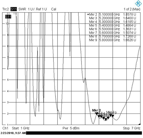
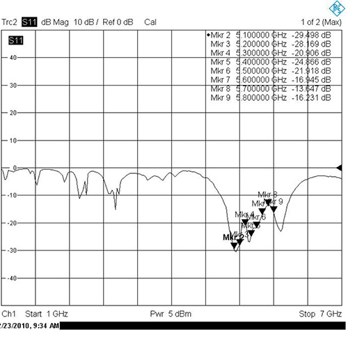
- 4.1 RETURN LOSS & VSWR
RETURN LOSS (port 1)
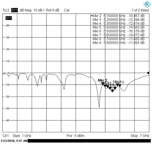
SWR (port 1)
RETURN LOSS (port 2)
SWR (port 2)
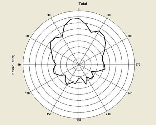
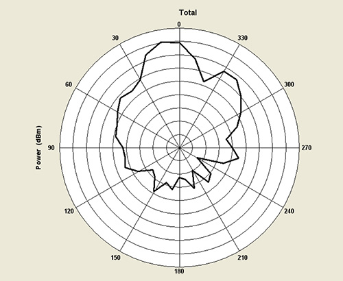
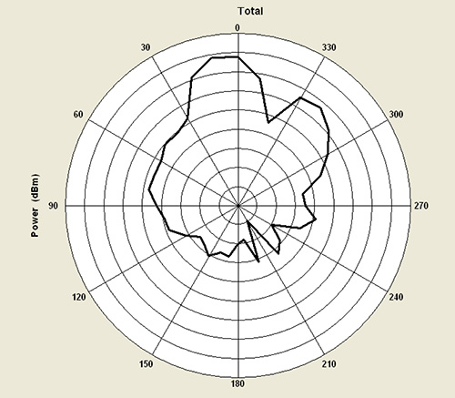
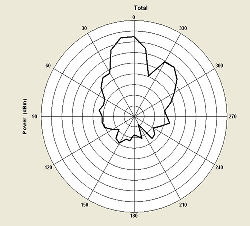
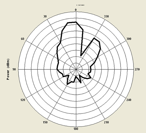
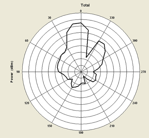
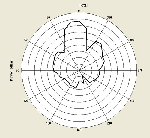
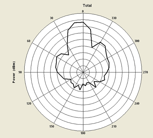
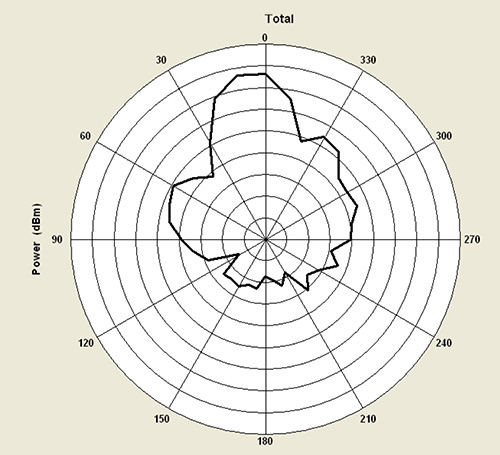
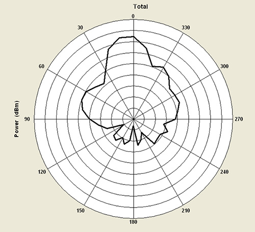
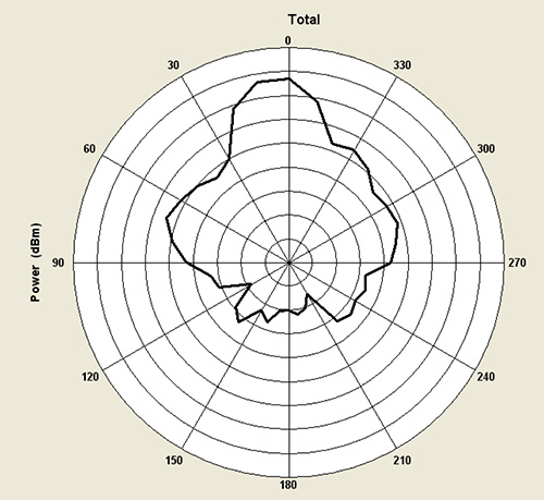
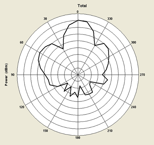
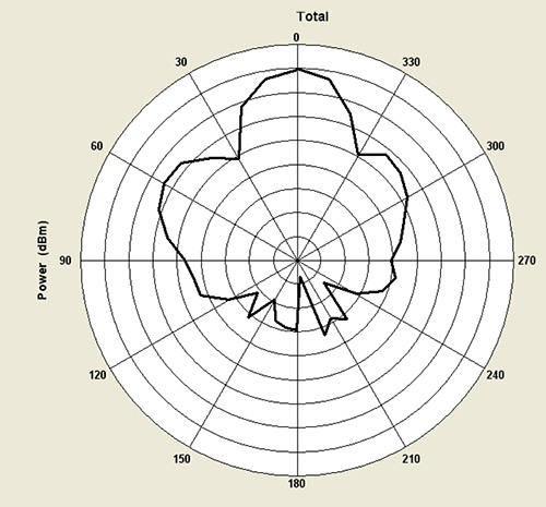
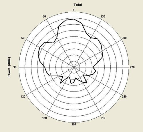
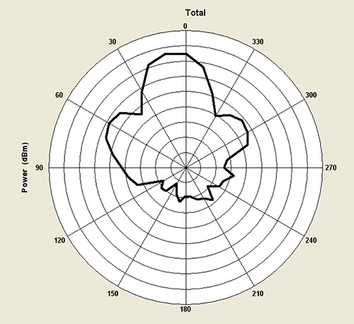
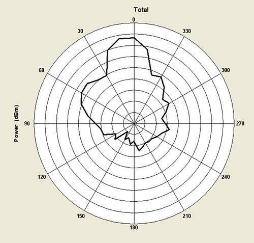
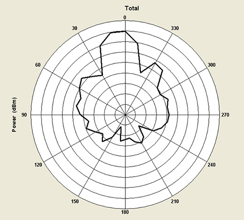
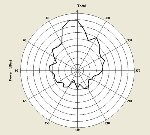
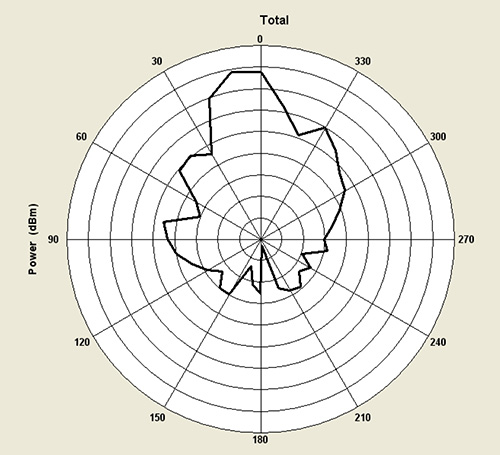
- 4.2 RADIATION PATTERN
4900 GHz (port 1)
5000 GHz (port 1)
5100 GHz (port 1)
5200 GHz (port 1)
5300 GHz (port 1)
5400 GHz (port 1)
5500 GHz (port1)
5600 GHz (port1)
5700 GHz (port 1)
5800 GHz (port 1)
5900 GHz (port 1)
4900 GHz (port 2)
5000 GHz (port 2)
5100 GHz (port 2)
5200 GHz (port 2)
5300 GHz (port 2)
5400 GHz (port 2)
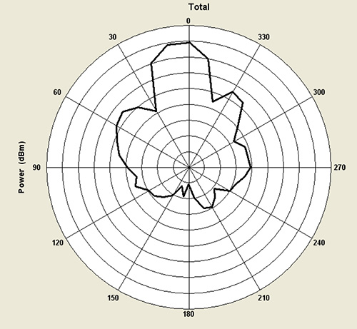
5500 GHz (port 2)
5600 GHz (port 2)
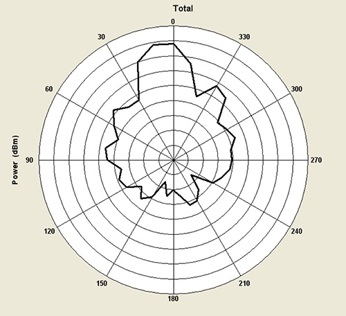
5700 GHz (port 2)
5800 GHz (port 2)
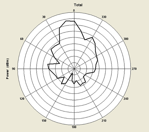
5900 GHz (port 2)
- 4.1 RETURN LOSS & VSWR